


Abstract - Waveform refresh rate, also known as waveform capture rate, refers to the number of waveform refresh per second, the unit is waveform number per second (wfms/s). Waveform refresh rate is an important indicator to measure the performance of oscilloscope. Higher waveform refresh can improve the display quality of oscilloscope, catch more occasional abnormal signals, improve the accuracy of measurement.
Index Terms – Waveform refresh rate, Waveform capture rate, Capture cycle, Sampling time, Dead zone time, Oscilloscope.
I. What is the waveform refresh rate?
Waveform refresh rate refers to the number of waveform refresh per second (wfms/s).
In general, waveform refresh rate of oscilloscope is also considered as waveform capture rate, because oscilloscope is like a high-speed camera, capturing and processing signals constantly, and then displaying the signal on the screen in the form of waveform image. The continuous captured signal reflected on the oscilloscope screen is the constantly refreshed waveform image. The time interval between each capture and the next capture is a capture cycle. The waveform capture rate is the number of captured waveforms in unit time (1s), which reflects the speed of capture signal of oscilloscope.
Compared with the bandwidth or sampling rate of oscilloscope, waveform refresh rate is often not the primary index that people pay attention to. The constantly changing waveforms on the display create the illusion that all signals have been observed. However, this is not the fact. In measurement, we often find that some abnormal signals with small probability that cause system failure cannot be observed by using the oscilloscope with low refresh rate, which will affect engineers' judgment on the problem seriously. However, the oscilloscope with high refresh rate can make the occasional small probability abnormal signal in a glance.
It can be seen that waveform capture rate is an important index that cannot be ignored. In this paper, we will introduce the influence of waveform refresh rate on oscilloscope measurement results.
II. Working principle of oscilloscope
As shown in the figure below, is the working process of oscilloscope. The analog signal collected by the probe first enters the vertical amplifier system through the input channel, and then quantifies as a digital signal through the A/D sampling. The signal is collected to the memory according to the trigger condition. After sampling, the CPU unit of the oscilloscope will process and calculate the data and display it on the screen before starting the next sampling.

Figure 1. Working process of oscilloscope
Oscilloscope acquisition waveform, storage, processing and displaying waveform constitute a complete capture period, each capture period includes sampling time and dead zone time.
1. Sampling time - The time to complete the collection and storage of a trigger is called the sampling time. The sampling time is the display and acquisition window of the oscilloscope, which can be calculated by multiplying the normal basis by the horizontal grid number of the screen.
2. Dead zone time - The time to process and display the waveform is called the dead zone time. The sampling and triggering of oscilloscope are mainly accomplished by hardware devices, and its speed is very fast. The processing involves a large number of calculations, and its speed mainly depends on the calculation rate and algorithm architecture of the processing chip. Since the speed of data sampling is much greater than the speed of data processing, sampling has to be stopped during data processing, which results in all waveforms during data processing to be lost because they are not collected.

Figure 2. An entire capture cycle
III. Influence of waveform refresh rate
Since the oscilloscope does not sample data during the dead zone time, the waveform captured by the oscilloscope has omissions, so reducing the percentage of the dead zone time in the capture cycle will help reduce signal omissions.
As shown in the figure above, the capture period of the oscilloscope is the sum of Ta (sampling time) and Td (dead zone time), and the waveform refresh rate is U:

The percentage of dead zone time in the capture cycle is:

Although as mentioned earlier, the dead time of the oscilloscope is much larger than the sampling time by several orders of magnitude. But according to the above formula, we can see that the higher the waveform refresh rate supported by two oscilloscopes with the same sampling time, the lower the percentage of dead zone time in the capture cycle, and the less the missing signal.
Let’s take a look again. The occasional low-probability abnormal signals that plague engineers mentioned at the beginning of this article. If these abnormal signals are hidden in the dead zone time period and are not captured and displayed by the oscilloscope, it will cause the observer to make wrong judgments. 
Figure 3. Abnormal signals
In order to reduce the omission of occasional abnormal signals during the observation period, it is necessary to increase the probability of the oscilloscope capturing occasional abnormal signals as much as possible. Let's look at the relationship between the probability of the oscilloscope capturing occasional abnormal signals and the waveform refresh rate.
Assumption:
t is the observation time, unit s
R is the probability of abnormal signal generation
Pt is the probability that the oscilloscope can capture the abnormal signal during the observation time t
Then every time the oscilloscope captures a signal, the probability that the abnormal signal can be collected is:

In the observation time t,
The number of times the oscilloscope can capture the waveform is: 
The probability that the oscilloscope cannot capture the abnormal signal continuously is:

The oscilloscope can capture the probability of an abnormal event:

It can be seen that when the observation time t and the probability R of abnormal signal generation are fixed, the higher the waveform refresh rate U, the greater the probability that the oscilloscope can capture the occurrence of abnormal events, and the more accurate the oscilloscope's measurement results.
The following figure shows the influence of different waveform refresh rates on the probability of capturing incidents

Figure 4. Waveform capture rates affect capturing accidental events
IV. Measurement of oscilloscope’s waveform refresh rate
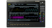
As mentioned earlier, the waveform refresh rate is an important indicator of the oscilloscope, so how can we know the actual refresh rate of the oscilloscope? Let's take the latest DS70000 oscilloscope from RIGOL as an example to introduce how to measure the waveform refresh rate of the oscilloscope.
Whenever the oscilloscope DS70000 samples a frame of waveform, it will output a pulse signal at the AUX OUT interface on the rear panel. We can determine its waveform refresh rate by measuring the AUX OUT output signal.
1. Prepare the tools needed for measurement
A DS70000 is used as the oscilloscope under test, an MSO8000 is used as a measuring oscilloscope, a DG992 is used as a signal source, a BNC cable and a radio frequency coaxial cable with a BNC interface on one end and an SMA interface on the other end.
2. Build a test environment
(1) Connect the CH1 interface under the front panel of the DG992 to the input channel CH2 under the front panel of the DS70000 through a BNC cable.
(2) Connect the SMA interface on one end of the RF coaxial cable to the AUX OUT interface on the rear panel of the DS70000, and the BNC interface on the other end to the input channel CH1 under the front panel of the MSO8000 test oscilloscope.

Figure 5. Set up a test environment
3. Set parameters for measurement
From the previous formula, we can see that the waveform refresh rate of the oscilloscope is related to many factors, especially when choosing different levels of time base to select the gear, the waveform refresh rate is different.
(1) First, set the DG992 signal source to generate a sine wave with a specified frequency bandwidth, and urn on the cymometer of the input channel CH1 of the oscilloscope MSO8000 at the same time;
(2) Then adjust the horizontal time base of DS70000 to different gears and read the counts of the cymometer on the MSO8000 respectively to obtain the waveform refresh rate of DS70000 under different conditions.
After the measurement, it can be seen that the waveform refresh rate of the RIGOL DS70000 series oscilloscope can indeed reach more than million wfms/s.

Figure 6. Waveform refresh rate: 10,000 wfms/s

Figure 7. Waveform refresh rate: 1,000,000 wfms/s
V. Capture small probability of occasional abnormal signal
How does the DS70000 perform in a scenario where it captures small probability of occasional abnormal signals?
The figure below shows a mixed waveform composed of one hundred thousand 10MHz sine waves superimposed on one 30MHz abnormal sine wave with low amplitude. There are obvious visual differences in the probability of displaying abnormal waveforms in an oscilloscope with a refresh rate of 100,000 wfms/s and an oscilloscope with a refresh rate of 1,000,000 wfms/s.

Figure 8. Waveform refresh rate: 10,000 wfms/s

Figure 9. Waveform refresh rate: 1,000,000 wfms/s
It can be seen that the small probability of abnormal signals is visible in front of DS70000 which supports 1,000,000wfms/s waveform refresh rate.
VI. Conclusion
The waveform refresh rate is a key indicator to measure the performance of the oscilloscope. An oscilloscope with ultra-high refresh rate can reduce the omission of the acquired waveform, increase the probability of occasional abnormal events in the captured signal, and improve the efficiency of troubleshooting. It is an engineer's right-hand man.
The DS70000 series digital oscilloscope independently developed by RIGOL relies on the UltraVisonIII hardware platform built by RIGOL engineers for ten years and has achieved a million-level refresh rate through a unique patented algorithm, reaching the industry's leading level.
The DS70000 series of digital oscilloscopes have fully explored the excellent performance of RIGOL’s self-designed "Phoenix" oscilloscope dedicated chipset and achieve the highest domestic 20GSa/s sampling rate and 4GHz real-time bandwidth. In addition to the improvement of hardware indicators, DS70000 series digital oscilloscopes also provide a variety of humanized designs, which I believe will definitely bring you a super high-quality experience.
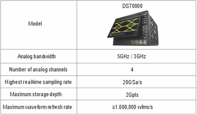
Figure10. Oscilloscope DS70000